
A controlled heating and cooling cycle applied to a welded joint after welding — held at a set temperature for a set time, then cooled under control. Here’s what it is, why it matters, and how it’s carried out in the field.
Exact values depend on the material, thickness and the applicable code / WPS.
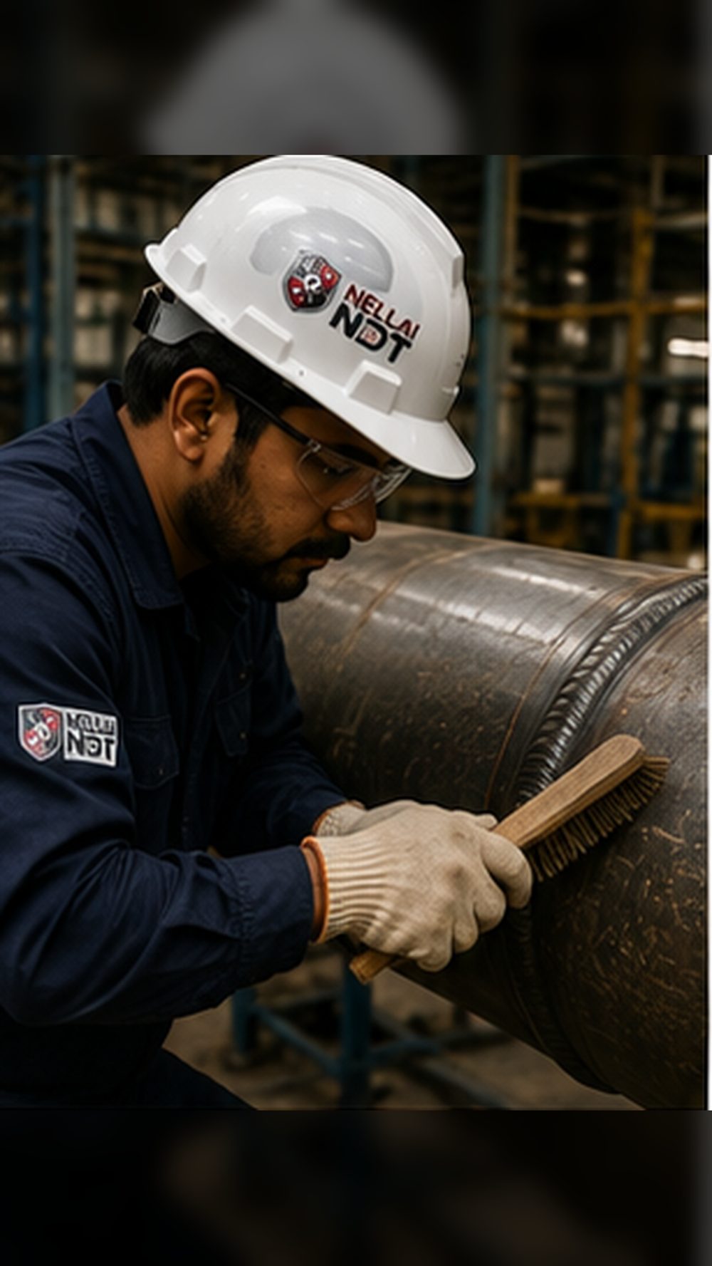
Clean the weld and the surrounding surface — remove scale, slag, rust, paint and oil by wire-brushing — so the heaters and thermocouples make good, direct contact with the metal.
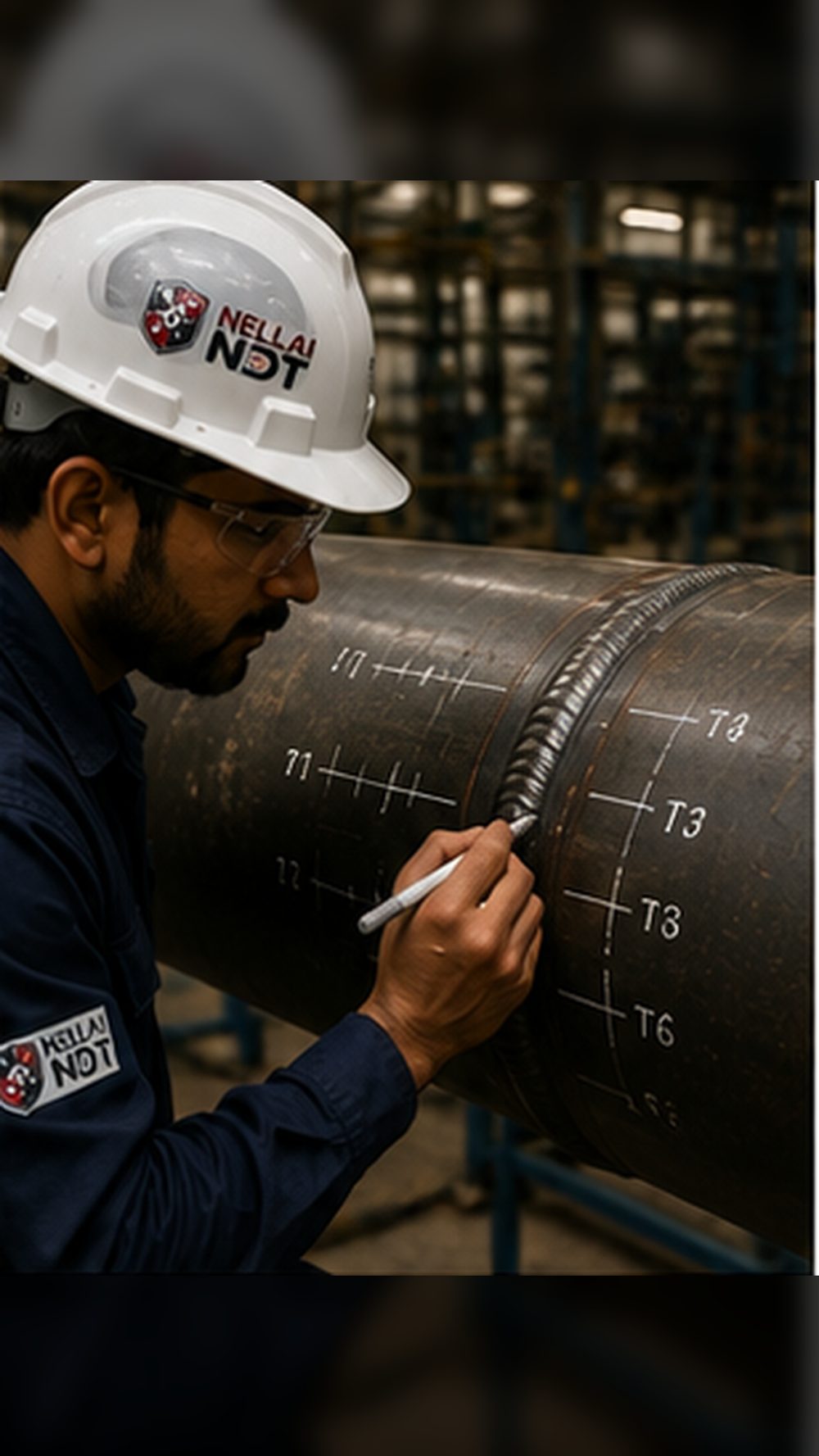
Mark out the thermocouple and heater positions around the joint to the PWHT procedure, setting the soak band, the heated band and the gradient-control zones.
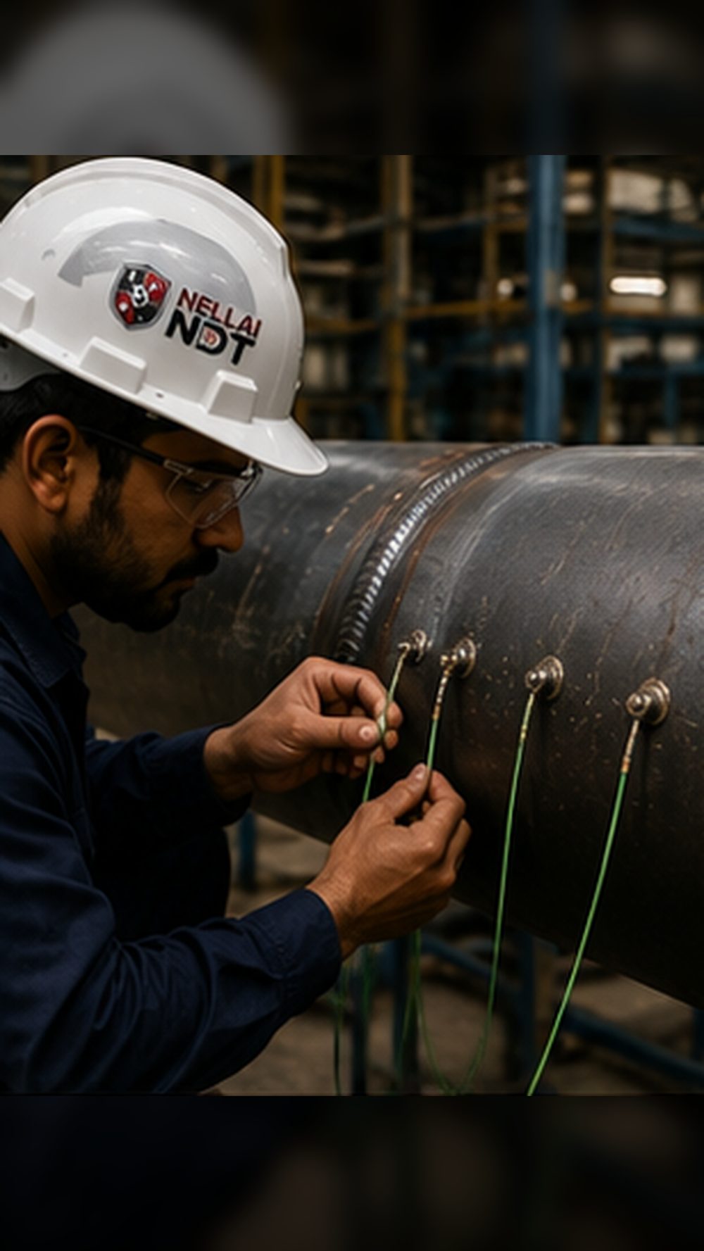
Attach thermocouples at the marked points (capacitor-discharge welded) to control the cycle and continuously record the actual metal temperature.
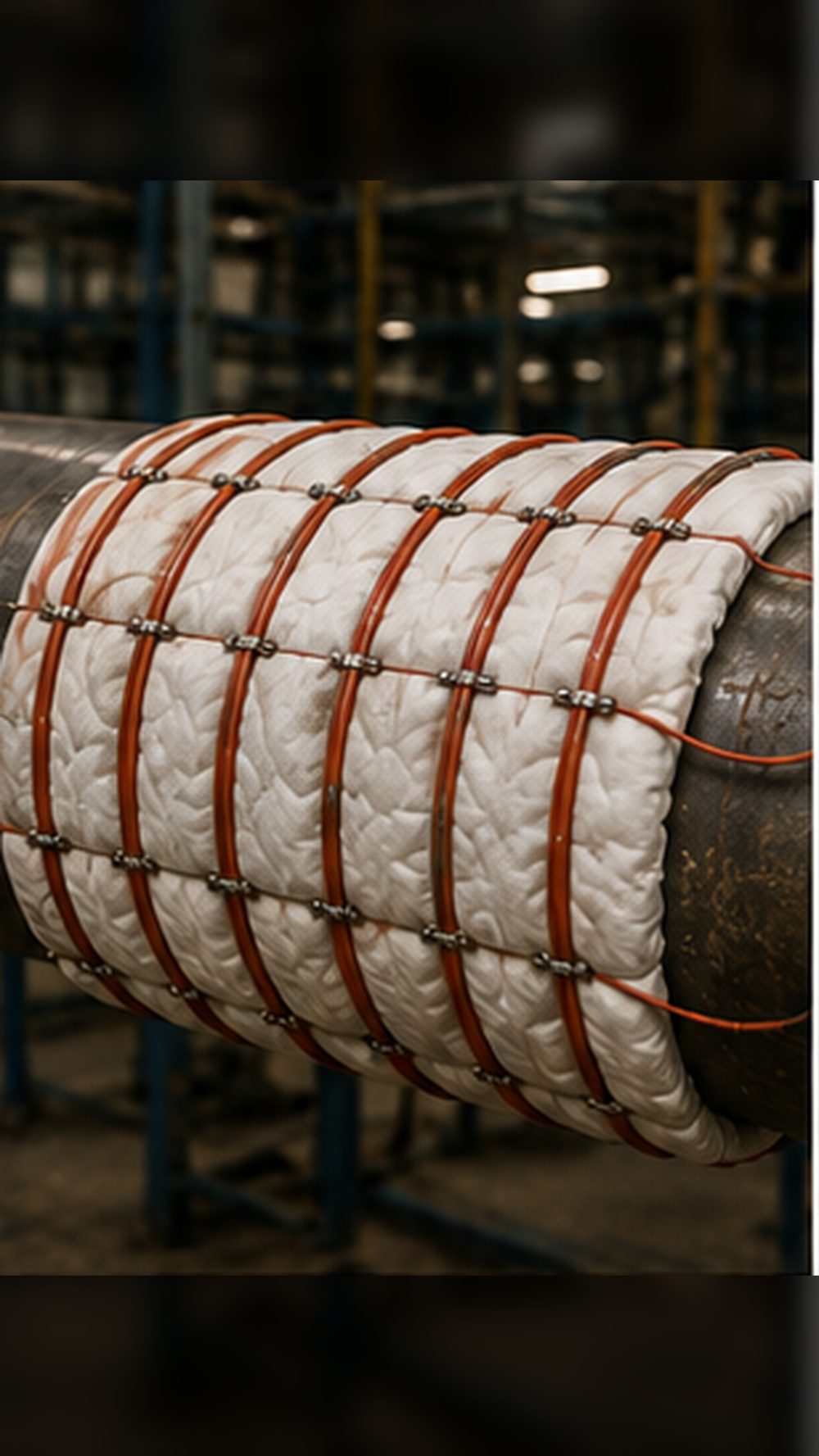
Wrap flexible ceramic-pad electrical heating elements around the heated band and secure them firmly against the pipe.
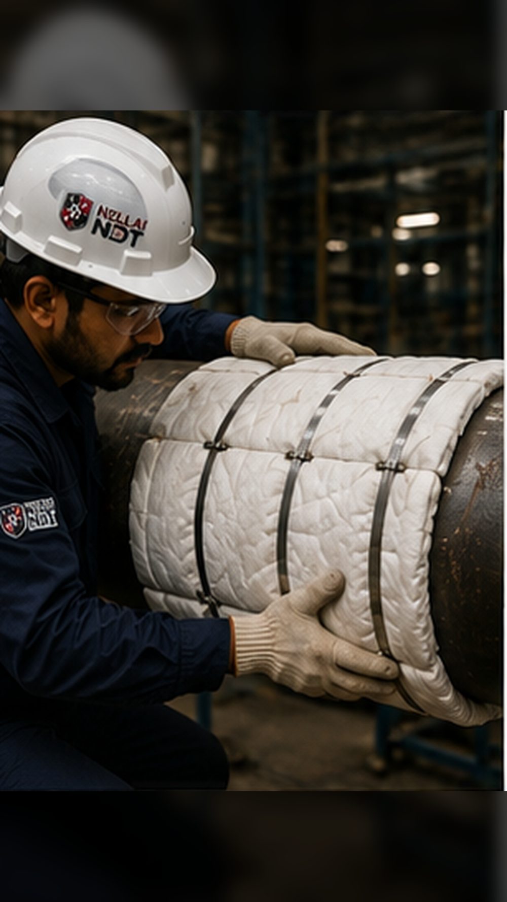
Cover the heaters with ceramic-fibre insulation blankets and band them tightly — this retains the heat and controls the temperature gradient along the pipe.
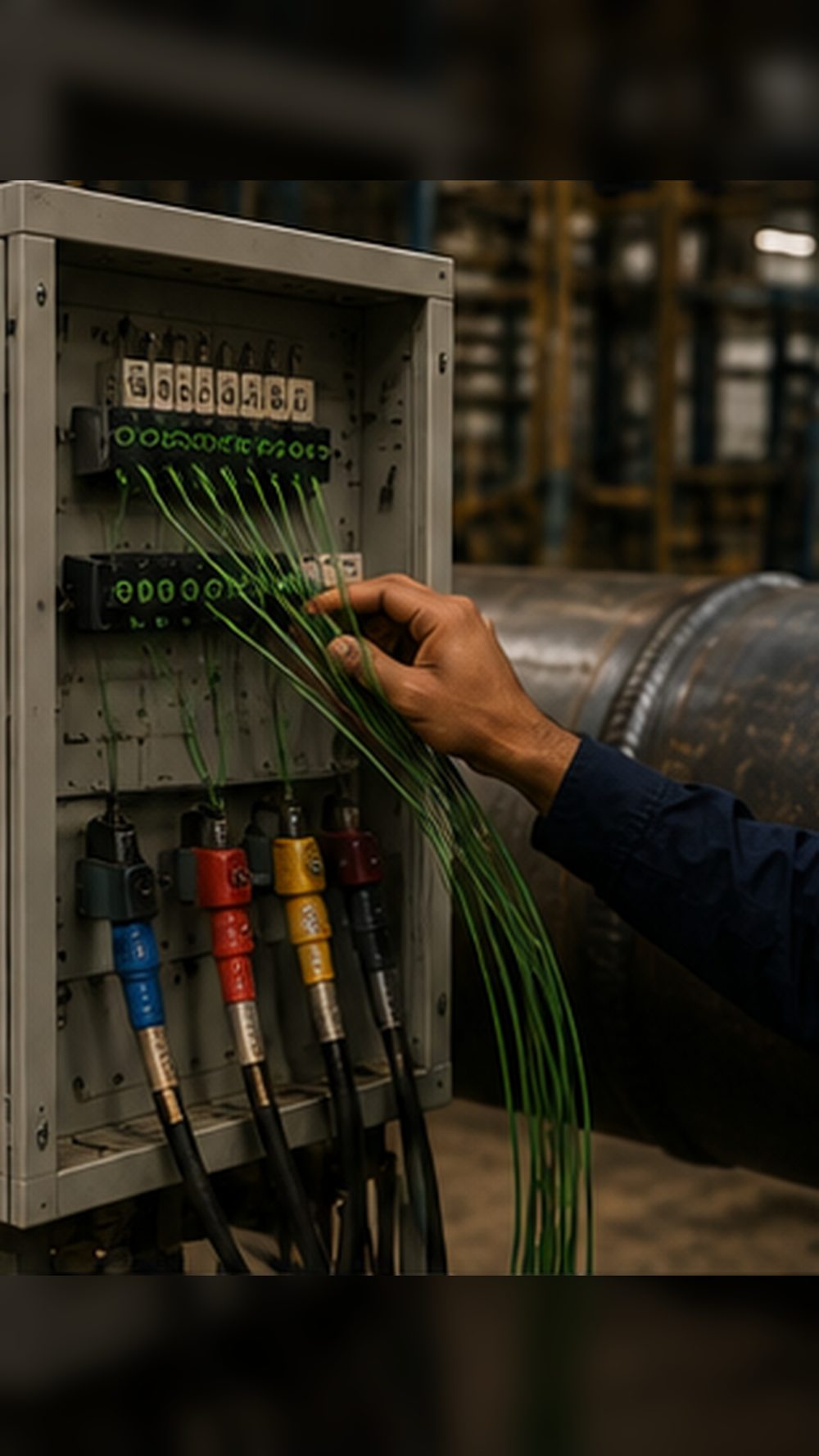
Connect the heater power leads and thermocouple cables to the console, then check every zone and connection before switching on.
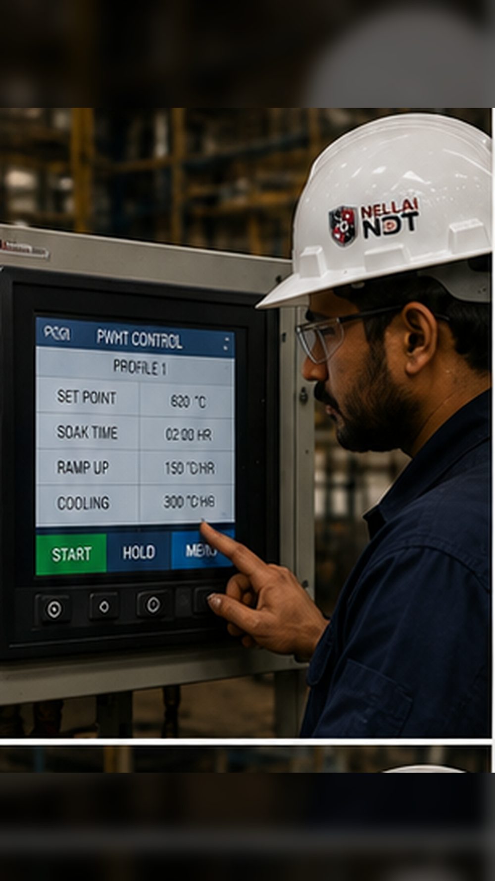
Program the profile on the controller — set-point (soak) temperature, ramp-up rate, soak time and controlled cooling rate — from the WPS / PWHT procedure.
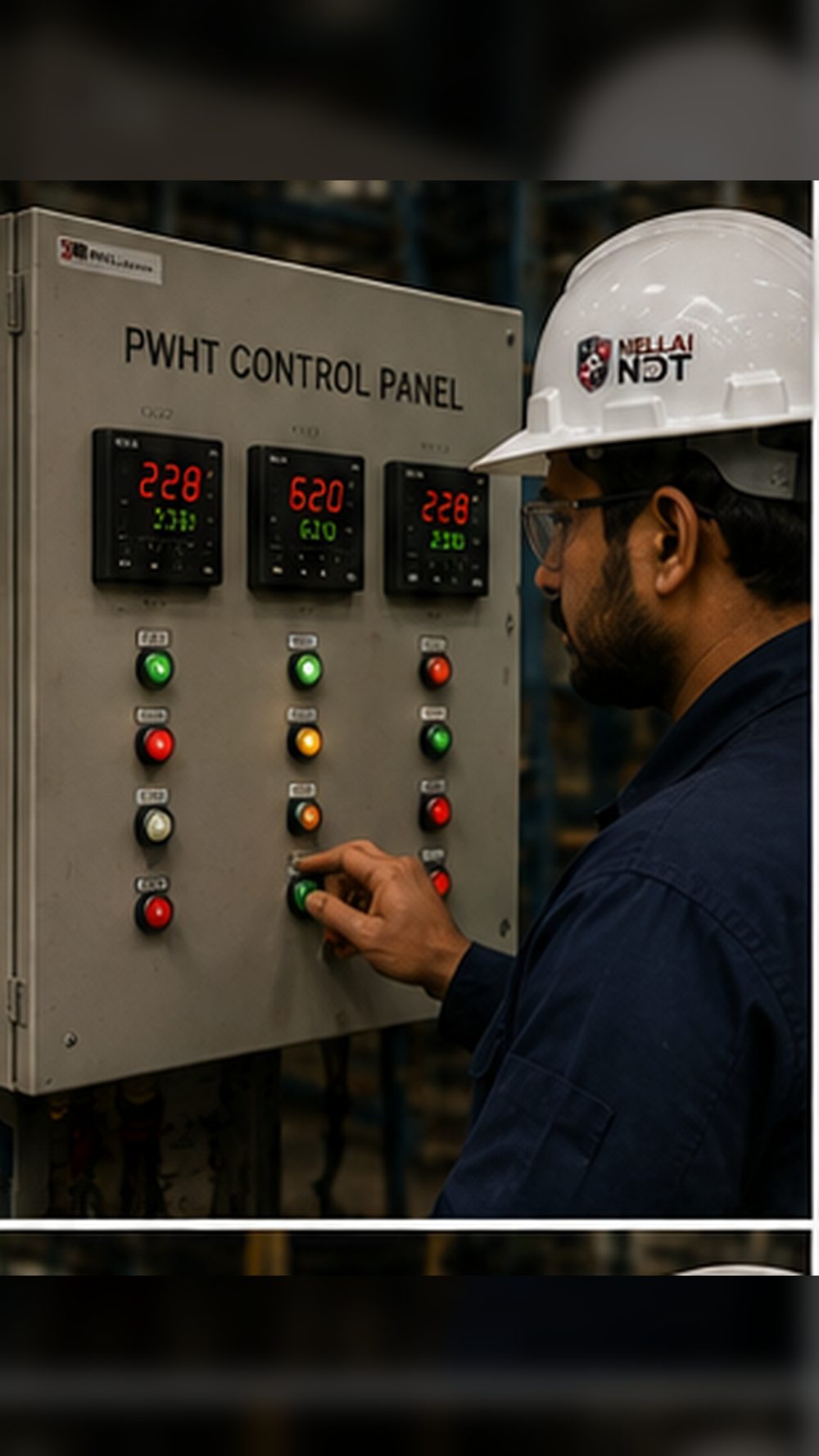
Energise and raise the temperature to the soak point at the controlled rate, watching each zone’s controller stay in step.
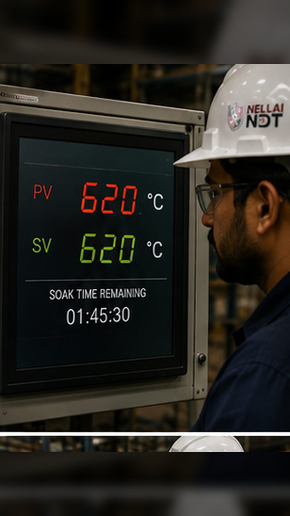
Hold the joint at the soak temperature for the required time — the “soak” — keeping every zone within tolerance throughout.
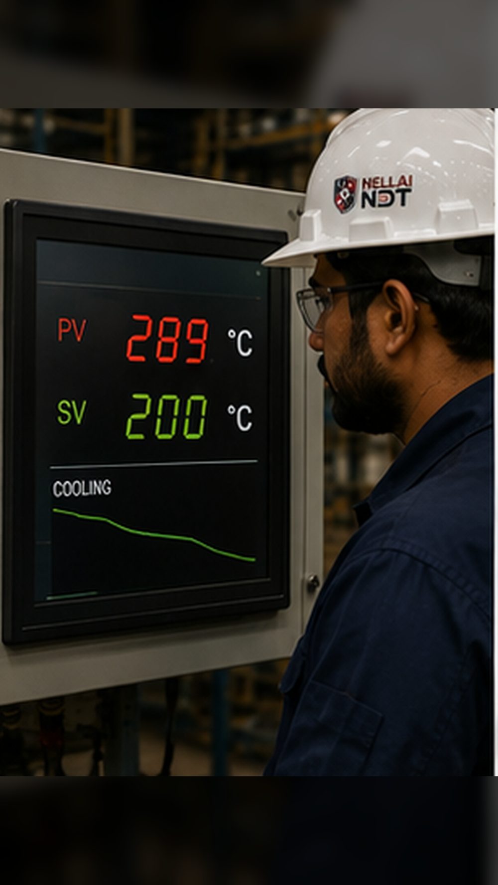
Cool at the specified controlled rate down to the release temperature. Never cool faster than the procedure allows.
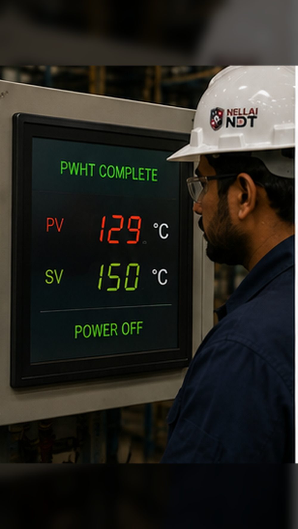
When the cycle is complete and the metal has reached a safe temperature, power the heaters down.
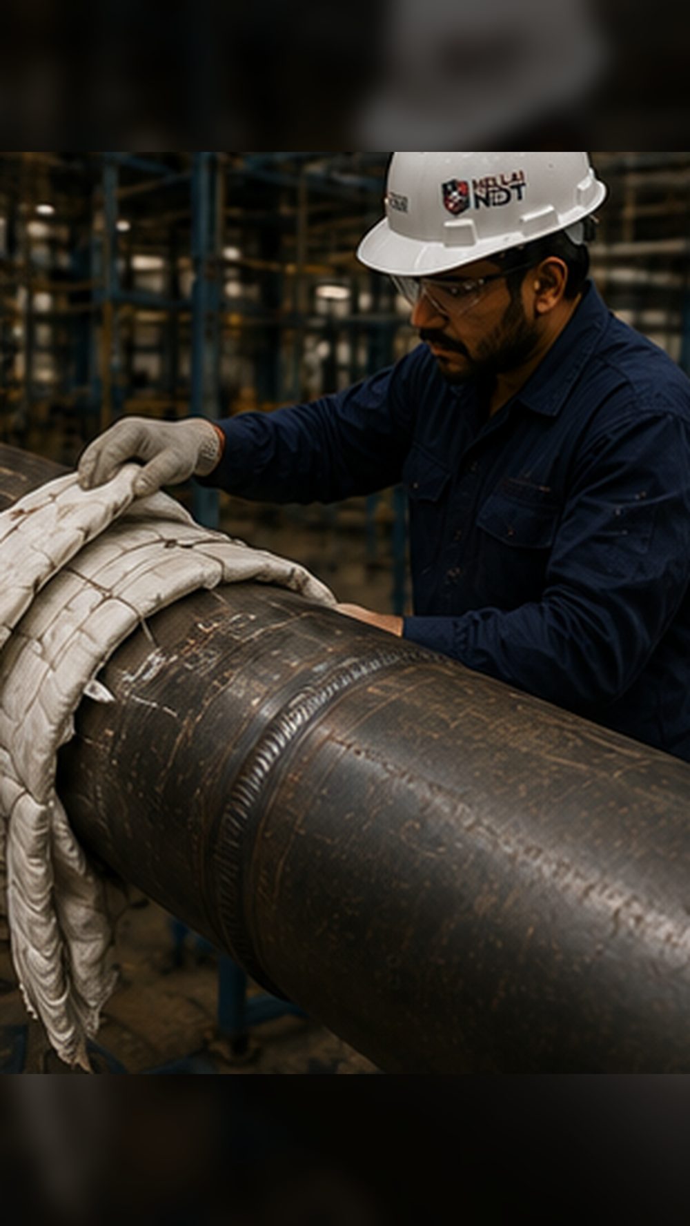
Strip off the insulation and heaters. The joint is now ready for post-PWHT checks — such as hardness testing — and a final review of the recorded temperature chart.